Antdroid
Project Overview
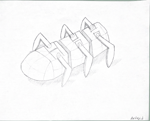
Antdroid is a hexapod robot I designed, manufactured, coded, and documented during a semester-long course at Duke. The design constraints required there to be no wheels and a maximum of 8 motors. By the end of the semester, our robot was expected to dance and then compete in a race. Antdorid was entirely 3D printed, developed over the span of 6 prototypes, required biweekly presentations, and a few all nighters.
Technical Details
Hardware Components
- Raspberry pi 4B+
- PYLX16 A motors
- LewanSoul Serial Bus Servo Controller Board
- TalentCell 12V 3000mAh Rechargeable battery
- 10A Stepdown DC to DC Buck Converter
Software
- Python
- C++
Manufacture
- Ultimaker 3D-Printers
- Solidworks
- Cura
Challenges and Failures
Integrating the pylx16A motor library to the Raspberry Pi proved an arduous task. What seemed like a plug-and-play option ended up taking weeks to work. After numerous Sudo commands, trying all different versions of the Raspberry Pi operating system, help from online forums, etc. I was able to determine that there was a braille compatibility issue between the library and my monitor. I am not sure why this feature existed and was not communicating but simply bypassing the execution of this feature allowed the library and code to run seamlessly. A week long struggle was solved in seconds.
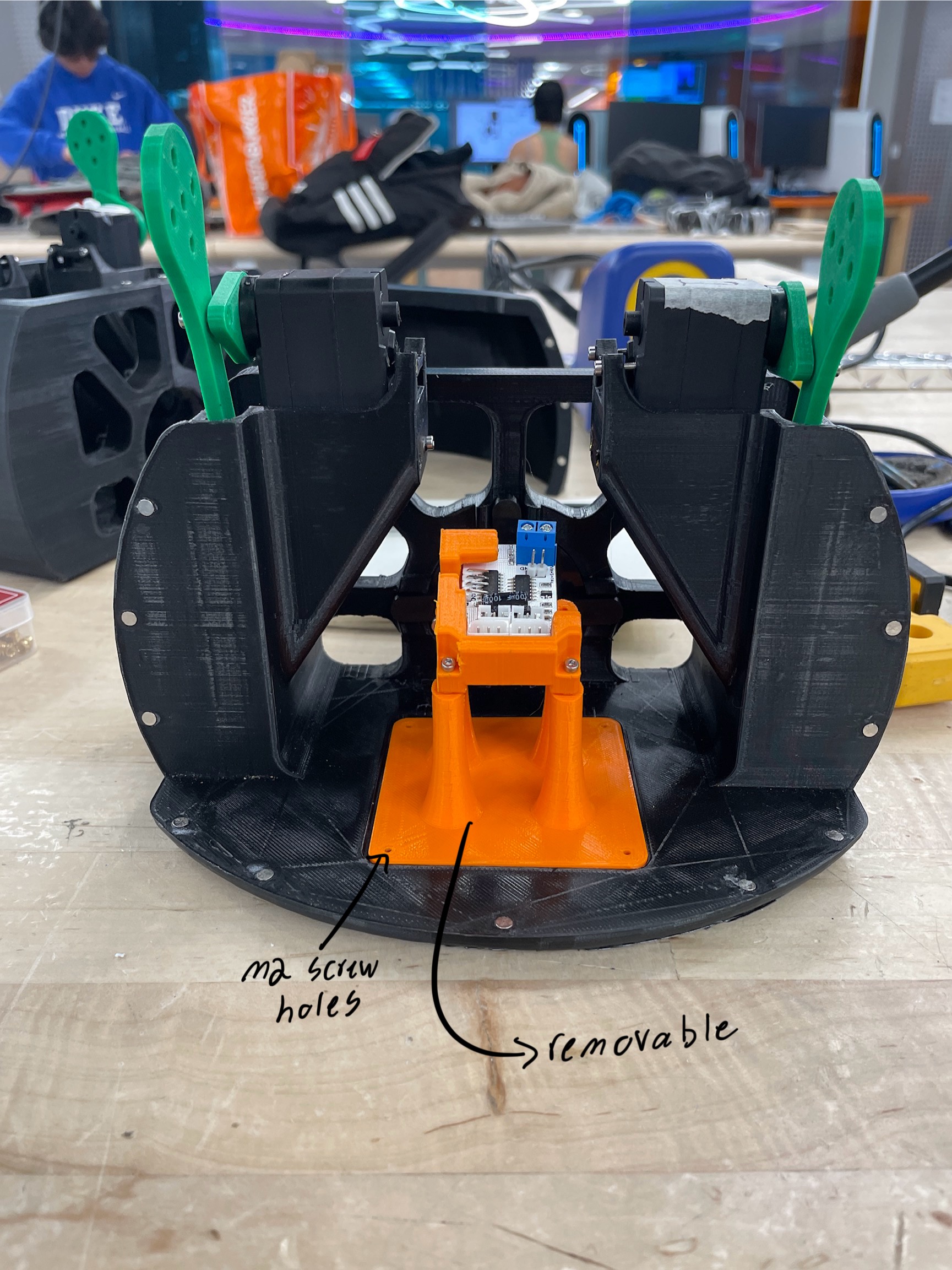
With the software now working, integration with the hardware could commence. The Raspberry Pi and motors ran off of different voltages (12v and 7.4v respectively) so a buck voltage converter was required to run the motors off of the same batteries. Quickly there were lots of wires to run the system and if even one was unplugged, functionality would cease to exist. Therefore, when I ran into issues with the robot, I created a methodical approach to solving it.
First, I would check all hardware connection points. There were a lot of moving parts to this robot so I would ensure nothing was getting stuck, had become unfastened, or broke.
Next, an investigation of all wires and their connections would begin. I wasted two days trying to solve an issue with the robot that was resolved because I fully plugged in a wire. I thought there was a code issue and only addressed the software side which was misinformed and a poor problem solving process.
Assuming the latter two did not solve my dilemma, my next step was jumping into the code. If there was a problem with execution displayed in the terminal, online forums would be my first stop to research a solution. Despite being an individual project, the class was very communicative so reaching out to our online forum asking for help was also an effective strategy. If my problem was however with the code not executing what I wanted with the robot, trial and error would be my approach. Perhaps my sin wave functions were incorrect or timing off. The only way I could work on fixing these problems was editing the code, running the script, recording the results, and making changes accordingly.
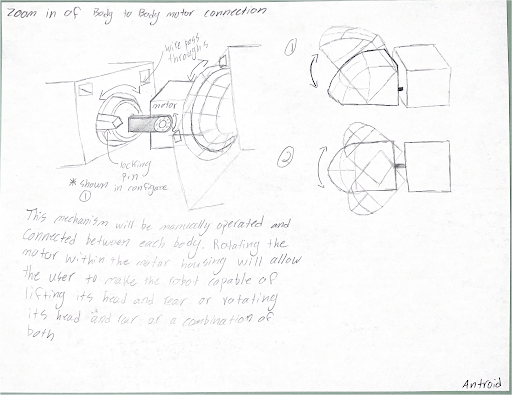
The most notable failure during the manufacturing process was the section mobility idea. The connecting pieces between the sections of the robot proved more tedious than anticipated and taught me an important lesson of not spending too much time on non critical components. You can always return to an innovative, riskier idea, but ensure a minimal viable product is accomplished first.
The first design enabling section mobility involved securing the motor into a circular profile housing. This would allow the motor to rotate so that the user could choose to move the section up and down or side to side. Locking the motor in the specific orientation required the most prototyping. Originally, the locking mechanism used spring loaded pegs that would fit into four groves 90 degrees apart. The locking mechanism design worked in theory however there was minor rotational play with the motor and proved quite difficult to engage and unengage. A new design was necessary.
Wanting to not need to reach my fingers into the compartments, I devised a system using magnets that lock the circle in 90 degree rotational movements. Then, a tightening bolt locked the system entirely. The magnets worked like a charm and allowed for super fast rotational adjustments by the user.
While this design worked in perfect testing environments, tolerancing issues made for the design to not be effective when the antdroid was trying to walk. Because the robot had to balance on three legs at a time, a rotational force concentrated at the section mobility locations. While the magnets were strong, there was not enough friction to prevent rotation and the robot would struggle to walk.
To fix this issue, rods were installed to rigidly attach the section together. While this prevented the robot from having sectional movement, it allowed for high quality walking procedures. I am still proud of the prototyping and development and know if there was more time in the semester, I could have reprinted and had a slight redesign to ensure the sectional mobility.
The final project of the class was to create a video of our robot. Drawing inspiration from the hundreds of documentaries I fill my time watching, I thought making a nature documentary of Antdroid would be a great way to craft a story, be engaging to the audience, and challenge me to produce a video I have never made before. Thankfully during the entire build process I was adamant to document every step and use my GoPro to take video. Using the advancements in AI, I used a program that would allow me to write a script and then have David Attenborough commentate. No documentary is complete without his serendipitous voice.
Upon completion of the Antdroid, I began combining the video. Wanting the video to work on multiple levels and prove that Antorid was one with its surroundings, I desired to have most of my shots focused around the Duke Chapel. Thankfully Duke is a beautiful shooting location so the feelings of a grandier something bigger than all of us were easy to weave into the story.
I am incredibly proud of the final video product because it not only shows my engineering creation that I worked tirelessly on, but showcases my passion for nature and creative mindset. Engineering can be taken so literally so I strive to always add flare and an outside perspective never before seen.
Reflections and Takeaways
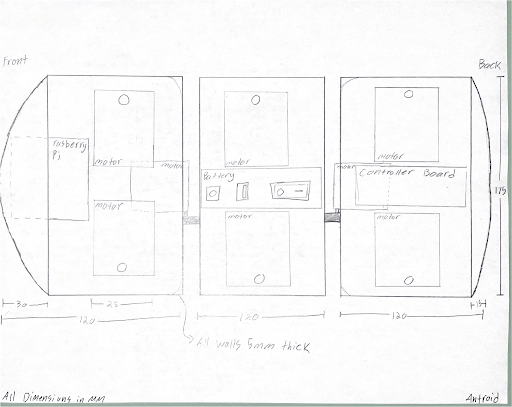
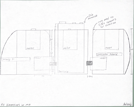
I spent two weeks brainstorming and drawing solutions to the problem of designing a robot. While Antdroid was one of my original ideas, I knew that I needed to exhaust my creative mind and push out as many solutions as possible to feel comfortable with my final choice. Once I weighed my options and Antdroid was the winner, the drawing did not finish there. Building the robot in my mind and translating those ideas onto paper allowed me to make key dimension decisions early in the process. To add on, creating organic shapes and complex movement structures takes time and experimentation. Putting in the effort to draw to scale and consider exactly what I wanted my robot to resemble meant that once I started my CAD, I was just following a well laid out plan.
With biweekly presentations and a culminating journey video, I was pushed to capture video and pictures throughout the entire journey. At the start of the project, I did not know what story I would craft, but could not let that limit the media I captured. So, I got in the habit of recording anything and everything important, ensuring the quality would be high enough for my eventual video. Showcasing all of the work in a documentary was a fun and artistic way to share my robot’s journey. While my video does not showcase all of the nitty-gritty details of the robot, the artistry of the film speaks to how I wanted my robot to be beautiful and natural.
Diligent note taking was another important part of documenting. In the beginning, I would have my computer to take notes, but found this quite annoying as I couldnt take great notes when my hands were oily or covered in glue. In response, I learned how to take great notes on paper about my project and would then transcribe the notes onto an online database. While this seems trivial, taking quick diligent notes about tolerance issues, print failing because of one section, or a new idea took time to learn, especially because I would need to come back to these notes even when a large amount of time passed. Using consistent and accurate terminology, along with building a consistent note taking habit yielded a much higher level of success.
Creating all of the presentations (linked below) was a great way to summarize my thought process and extract other people’s ideas. I am glad that I did not try to make these presentations beautiful, per se, I kept them simple and too the point. However, I prioritized working on my robot’s structure than the presentations and there were a few times that I did not hit the quality mark I wanted. I was presenting to the entire class and poor resource management meant my presentations lacked high-quality depictions of my thinking or did not show the full extent of the work I had done.
With so many moving parts and thankfully, a lot of repeated parts, Antdroid advanced my skills of rapid prototyping. For starters, I had a lot of slide and press fits so finding the right diameter was essential to a successful robot. Since I wanted to test multiple dimensions at a time, I would employ clever labeling techniques that were part of the print so that I could easily refer back to the CAD dimension.
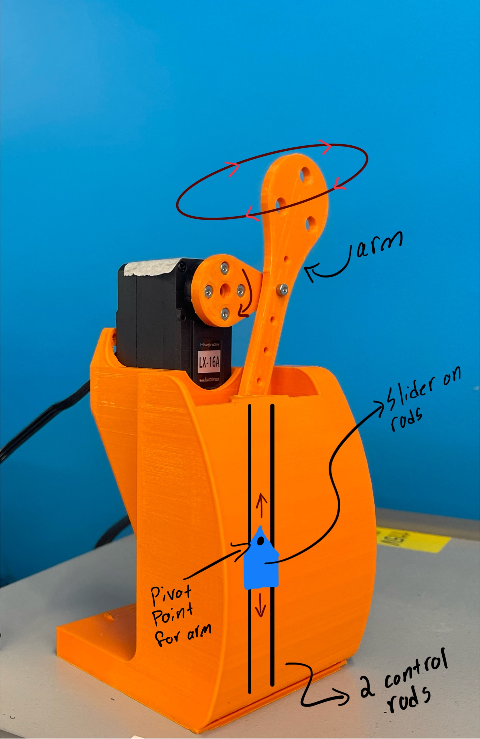
Furthermore, my elliptical walking mechanism took 8 prototypes before I had the perfect tolerances and design. To make this prototype, I just took the body that I had already designed and printed the component housing the elliptical drive unit. While this was effective to ensure my final design would work, I wasted tens of hours on prints only to find that I needed to extend the rods or redesign the slider. Had I just bit the bullet and designed a testing platform, I could have finished the elliptical drive much sooner and then start printing the body to test the final form.
Solidworks was the CAD program of choice for this robot design. I have used Solidworks since 2018 but have never created such a complicated and multiple piece design. Challenging myself to make organic parts, I pushed my design skills and am proud of how few right angles or non flowing sections of the robot exist. My favorite feature that I learned how to use is solidowrk’s equation tool and linking these equations to a notebook. Being able to store dimensions from one part to the next saved me hours when I realized a hole for my M2 screw should be 0.2mm smaller since there are around 50 of these holes. To go in and individually edit the dimension would have taken ages, but simply changing the dimension on my notebook took seconds.
I had never used C++ before this project. Since there was a custom library for the servo motors, learning a new language by referring to the documentation was slow, but a valuable lesson. With python and matlab, documentation is so expansive that I find myself really just relying on forums. However, I learned how to read documentation jargon and could answer questions for myself, instead of needing to go online. There is clear value to dedicating time to learning the fundamental commands and processes instead of jumping into code blindly. Also, I found myself commenting on my code much more to retain and remind me of what I was learning/ coding. I have extended this habit into more projects.
Fasteners, such as nuts and bolts, can be a great asset when assembling, but wow do they slow the manufacturing and assembly portion. An important engineering hard skill I walked away with was my focus on limiting fasteners. Wedges, magnets, or clever designing made my life easier and faster when working on the assemblies which will undoubtedly inform my future engineering designs.
The days where I could not connect to the PyLX-16A library were frustrating to say the least. Struggling to identify the problem, starting from scratch over and over, getting annoyed as fatigue grew, and getting mad that I could not solve what was seemingly a simple problem was making me resent the project. There was one night in particular where I was so fed up with the code, I thought, let me work on the voltage converter. I began playing around with the converter, was not getting the right readings, double, triple checked my multimeter but no matter what, could not get the converter to work. This was supposed to be the easiest integration, simply twist a dial until it read 7.4 V. When this converter failed to work, I left my desk in rage and just walked out of my house towards the forest. The moon was high in the sky as I left around 3am in the morning. Sitting and thinking away from my project was healing and allowed me to mentally take control of the project again. I was lost in the weeds during this week and learned a valuable lesson of exiting the project, taking a break, and coming back with a clear mind. All of my coding and converter issues were solved the next day.

